Robotics & Arduino
Bring code to life with physical computing! Build robots, control motors, and create interactive projects that move in the real world.
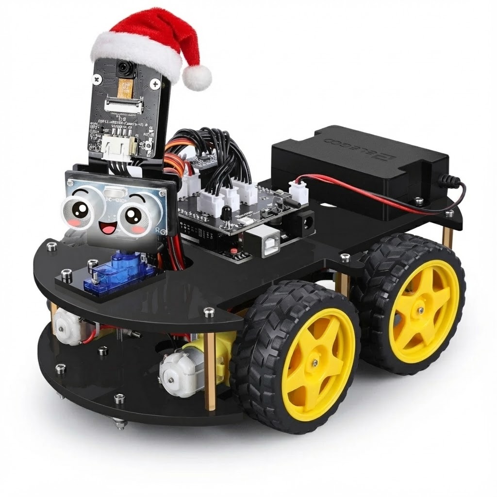
Customize a Robot Car with Code
Take control of a robot car and customize its behavior with code! Write Arduino programs to make it move, sense its environment, follow paths, avoid obstacles, and do whatever you can imagine.
What You Can Customize with Code
Movement Patterns
Code circles, zigzags, figure-8s, or any pattern you design!
Smart Navigation
Program how it reacts to obstacles - stop, turn, or find a new path!
Line Following Logic
Customize sensitivity and speed to follow any path you create!
LED Light Shows
Program blinking, flashing, or color-changing light patterns!
Camera Control
Code the camera to scan, follow objects, or take photos automatically!
Custom Behaviors
Combine sensors and motors to create unique robot behaviors!
CODE WALKTHROUGH
const int rightDirA = 4;
const int rightDirB = 5;
const int leftDirA = 7;
const int leftDirB = 8;
void setup() {
  pinMode(rightDirA, OUTPUT);
  pinMode(rightDirB, OUTPUT);
  pinMode(leftDirA, OUTPUT);
  pinMode(leftDirB, OUTPUT);
  Serial.begin(9600);
}
void loop() {
  // Logic to move robot forward
  digitalWrite(leftDirA, HIGH);
  digitalWrite(rightDirA, HIGH);
}Understanding how your code translates to physical robot behavior.
Custom Movement Patterns:
The code controls robot movement by adjusting the speed, direction, and timing of each motor.
- Circles: Run one motor at a slower speed.
- Zigzags: Alternating directions in intervals.
HARDWARE SETUP:
Bridges Arduino logic and high-power motors. Receives logic signals from pins defined as OUTPUT to enable motor driving capabilities.
Controlled via pins 7 & 8. The code variables leftDirA and leftDirB set the polarity for this motor.
Controlled via pins 4 & 5. The code variables rightDirA and rightDirB set the polarity for this motor.
const int trigPin = 12;
const int echoPin = 13;
const int rightDirA = 4;
const int rightDirB = 5;
const int leftDirA = 7;
const int leftDirB = 8;
const int obstacleDistance = 20;
void setup() {
  pinMode(trigPin, OUTPUT);
  pinMode(echoPin, INPUT);
  pinMode(rightDirA, OUTPUT);
  pinMode(rightDirB, OUTPUT);
  pinMode(leftDirA, OUTPUT);
  pinMode(leftDirB, OUTPUT);
  Serial.begin(9600);
}
void loop() {
  long distance = getDistance();
  if (distance < obstacleDistance) {
    turnRight();
    delay(500);
  } else {
    moveForward();
  }
}
long getDistance() {
  digitalWrite(trigPin, HIGH);
  delayMicroseconds(10);
  digitalWrite(trigPin, LOW);
  long duration = pulseIn(echoPin, HIGH);
  return duration * 0.034 / 2;
}
void turnRight() {
  digitalWrite(leftDirA, LOW);
  digitalWrite(leftDirB, LOW);
  digitalWrite(rightDirA, HIGH);
  digitalWrite(rightDirB, LOW);
}Understanding how your code translates to physical robot behavior.
Custom Obstacle Behavior:
The code uses sensor input to make decisions about robot movement. When an obstacle is detected, the robot automatically changes direction.
- Sensor Detection: Ultrasonic sensor measures distance to objects.
- Automatic Response: Code decides to turn when obstacle is too close.
HARDWARE SETUP:
Mounted on front of robot. Pin 12 triggers sound waves, Pin 13 receives echo. Measures distance by calculating time for sound to bounce back.
Stops when obstacle detected. Controlled via leftDirA and leftDirB variables (pins 7 & 8).
Continues spinning to turn robot away from obstacle. Controlled via rightDirA and rightDirB variables (pins 4 & 5).